Post
by Doug » Mon Mar 05, 2018 8:42 pm
You will only need to use two of the four ports on the Buildbotics Controller. Most likely, you will want to connect your X axis to the port labeled X and the Y axis to the port labeled Y.
Your motors have eight wires coming out of them because each coil has a separate pair. I noticed from your video that the motors are classified as bipolar series, so I'd recommend configuring them as bipolar series.
If you look at Appendix III in the manual, there is a nice article that explains how to wire up stepper motors. It says that you need the motor data sheet to hook up an eight wire motor.
I read the model number off of the motor and looked around on the web for the data sheet and found the same documents that you found, but did not find one for the exact model number. Having said that, I am guessing that your picture is correct. You could just wire it up as bipolar series and see what happens.
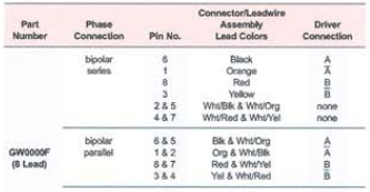
To do that, connect white/black (pin 2) to white/orange (pin 5) and white/red (pin 4) to white/yellow (pin 7). That configures the motor as bipolar series.
At this point, you can check your work with an ohm meter. The black wire (pin 6) should show a low resistance to the orange wire (pin 1), and the red wire (pin 8) should show a low resistance to the yellow wire (pin 3). These two pairs will make up your coils. Then confirm that you have a high resistance between the two coils, say from the black wire to the red wire. This doesn't completely confirm that it is right, but if you don't pass this test, then it is wrong.
Then make the following connections from the motor to the pre-made cable:
* black wire (pin 6) from the motor to red wire on the pre-made cable (this is A+)
* orange wire (pin 1) on the motor to the black wire on the pre-made cable (This is A-)
* red wire (pin 8) on the motor to the yellow wire on the pre-made cable (This B+)
* yellow wire (pin 3) on the motor to the purple wire on the pre-made cable (This is B-)
Once you get one motor wired up, plug it in to the Buildbotics Controller and try it out. Go to the motor configuration page for that axis and set the power mode to "when moving", the drive current to 3.3A (I read that off of the label on the motor), and the idle current to 0. Then try jogging the motor on that axis with the game pad. If the motor moves smoothly, you probably have it right. If the motor doesn't move, you probably have the wiring wrong. If the movement is rough and jumpy, you probably have the coils partially wrong or you have a bad connection.
If you want to reduce the likelihood that you wired it wrong before hooking it up, you can confirm the pairs with an ohm meter before making any connections. My wiring suggestions make the assumption that black and black/white make up the A coil, orange and orange/white make up the A' coil, red and red/white make up the B coil, and yellow and yellow/white make up the A' coil. If this is true, then you should measure a very low resistance between each of these pairs when nothing is connected. And, the resistance between any two coils should be very high.
If this doesn't get you there, you'll probably have to start reconnecting pairs through trial and error. This could get tedious, but eventually you will find a combination that makes the motors turn smoothly. If the motors turn smoothly, but backwards, just switch A with A-, or B with B-, but not both.
I hope this helps. Let me know how it goes.